
https://youtu.be/Kk1d-V8GrZE Tower 8.5 (Build 8572) Tower is software for static and dynamic structural analysis, concrete, steel and ti
Tower 8.5 (Build 8572)
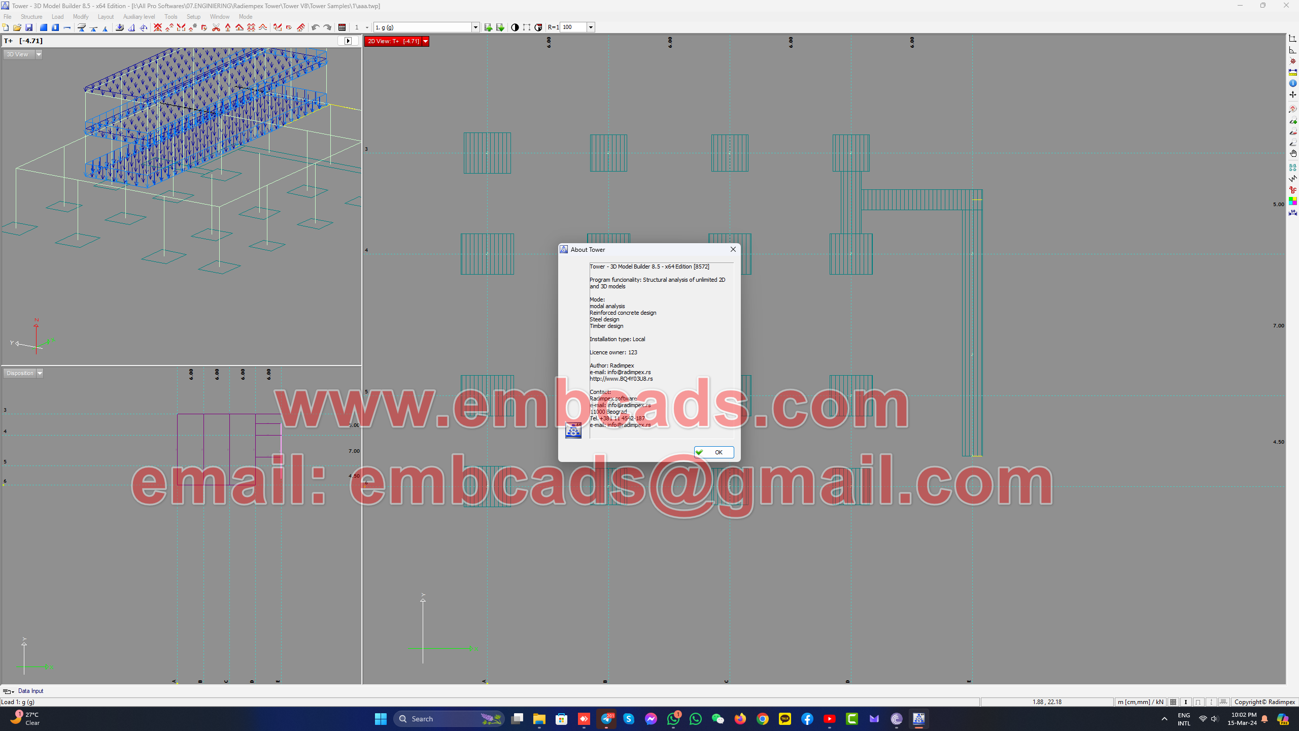
Tower is software for static and dynamic structural analysis, concrete, steel and timber design. It is specialized for universal analysis of influences in planar and space structures. By providing strong tools that are automated, integrated, all-inclusive and intuitive, this program enables the engineers to increase the speed and quality of designing. Version 8 is a high performance professional tool, based on experience lasting many years and on the latest knowledge and realization of the expert team, engineers and first-class programmers.
The most important new features are: combination scheme for road bridges (Eurocode regulations), “Direct orbit” which enables model rotation in the 3D view without calling the Orbit command …
Complete list of new features of this new version is:
- In the Load Combination Scheme command, in addition to the existing combination scheme for buildings, it is now possible to create a combination scheme for road bridges (Eurocode regulations)
- “Direct orbit” – enabled model rotation in the 3D window (3D Orbit) without calling the Orbit command. For enabling this feature it is necessary to check the check box “Direct orbit” in the “Settings – Functionality”, in the “Other” section. “Direct orbit” allows the model to rotate in the 3D window while holding down the left mouse button and moving the mouse.
- Generated load case reports can now include a list of (named) envelope load cases.
- As part of the “Information” command, which displays information about entities located under the mouse cursor, it is also possible to display information about nodes (number, coordinate, deformation vectors and oscillation form vectors)
- Change in the beam reinforcement adoption dialog – changing bars and other data in one of the zones no longer resets the user-defined segment lengths in other zones.
- New functions – “Calculation” and “Report” have been added to the masonry wall preview dialog, and the “Report” option has been added to the command line in the Masonry Wall Stress Control command.
- In the direct dynamic analysis (both seismic and dynamic load) in the damping setting parameters, the limits have been changed – alpha and beta damping factors now can be entered in the range of 0-100 and the unique damping coefficient from 0.001 to 0.99
- Added option to use arrow key combinations for command shortcuts (up, down, left right and Home and End) – if either Shift or Ctrl is pressed
- Among the commands for which it is possible to assign shortcuts, the commands for the Next load case and the Previous load case are included.
Released Tower 8.5 (Build 8535) which brings a quite number of new features.
The most significant new features brought by this new version are: seismic calculation of structures with non-linear behavior, IFC export has been significantly improved and the level of BIM compatibility has been increased, a new method (linear) has been added for combining seismic effects, mass grouping by levels with sloping surfaces is enabled,…
Complete list of new features in this update is:
- Seismic calculation of structures with non-linear behavior is enabled. This type of calculation is enabled for calculation procedures using the Lateral force method, or method of equivalent static load.
- From the generic EC8 regulation, four new seismic regulations (derived from the generic EC8 regulation for the transverse force method) were separated, Bulgarian, Croatian, Slovenian and Serbian. In the Serbian regulation, another default definition of the spectral curve described by the national annex was added.
- Significant improvement of the procedure for grouping masses by ceilings, which enabled the grouping of masses also by inclined surfaces (eg roof planes).
- A new method (Linear – “LIN”) has been added for combining seismic effects – an alternative to SRSS combining. This method enables the automated creation of seismic combinations that are made in accordance with EC8 EN 4.3.5.5.1. point 3. Eedx “+” 0.3 Eedy and 0.3Eedx “+” Eedy (with and without taking into account mass eccentricity)
- This method of combining seeks the highest possible value when adding up the absolute values of the influence of the seismic impacts, with one of them having a multiplier of 1, and all others 0.3.
- The option of automatically creating linear seismic load cases (“1+0.3”) after calculation has been added to the dialogs for seismic calculation according to EC regulations.
- Significant improvement of IFC export, which achieved an extremely high degree of compatibility of the exported IFC file with the programs Revit, Archicad, Allplan, etc. In addition, structural elements (slabs, walls, beams and columns) are associated with data related to volumes, surfaces , dimensions, materials, cross sections.
- It is possible to limit seismic model’s support multipliers (as well as the global support stiffness multiplier) only to the calculation of the modal analysis, and to perform the seismic calculation without taking them into account, enabling the reduction of the effects of “peaks” of influence in the foundations.
- Enabled creation of a moving load whose direction of action is specified in relation to the local coordinate system of the axis of the moving load. The moving load display in the dialog now matches the actual direction and orientation of the moving load on the first segment. Also, from now on, it is allowed that two loads have the same geometry, but it is necessary that their vector of action is different. (refers to line and surface loads).
- In the punching control of slabs at the end of the wall, added option for user input of the length of the edge zone of the wall has been introduced.
- EC8 Capacity Design – Changes in the check of exceeding the maximum percentage of tensioned reinforcement. If the adoption of reinforcement has not been carried out, the check is carried out with the computationally necessary. In case that there is required more tension reinforcement than is allowed, then the amount of compressed reinforcement is increased, so that their ratio stays at the limit. In the event that the adoption of the reinforcement has been carried out, the check of exceeding the maximum permitted percentage of the tensioned reinforcement is performed on the adopted reinforcement.
- EC8, Capacity Design – In the command for editing the critical zones, added option for multiple editing.
- For the surface load that acts over the system of line entities, it is possible to include the slab’s contour or slab’s hole contour as the member of the acting line entities system.
- In the EC8 Capacity Design reports, the display of data on the sensitivity factor and the coefficient of influence increase due to the consideration of second-order effects was introduced. The display of the VrdMax value was introduced, too.
- Improvement in the control of adopted reinforcement in beams concrete design. Now, when checking the coverage of the required reinforcement, another condition is also checked – condition when half of the angle bars from A1 and A2 are added to the corresponding ones belonging to A3 and A4 zones. In case that requirement is satisfied in this way, then it is considered to be covered.
- New options have been introduced in the load combining scheme: unification by simultaneity and unification by dominance.
- A new command has been introduced that can be used to convert walls into line (or point) loads.
- Four new “commands” (icons-switches) have been introduced – for instantly changing the visibility of beams, columns, slabs and walls (commands have been added in menu a and can be added as toolbar icons)
- Improvement in the export of 2D model assemblies – from now on, all existing auxiliary views of the model are also exported, along with its complex views are exported (only if all their subassemblies are exported).
- In the dialog for seismic calculation, it is possible to enter the Z coordinate of level of application of the seismic action (foundation or top of a rigid basement). This data is used to generate a report on the value of the total transverse force at that level (calculated by an approximate procedure)
- For glued laminated timber (material classes), the EN 14080:2013 regulations have been added to the timber material database and will be automatically added to the existing timber material database.
- In the modal analysis reports (in the oscillation period and oscillation shape reports), it is possible to display data on modal masses.
- In the Expert configuration, the maximum number of modal analysis tones has been increased from 250 to 900
- A change in the concrete design of the proxy entity, which makes it possible for the proxy entity to be calculated even if it has only one unknown armature in the section (in case there is at least one zone with known armature).
- Improvement in the display and orientation of the proxy entity cross section in the dialog as well as in its report.
- Marking (coloring) of combinations that contain at least one of the selected basic load cases has been introduced in the dialog for load combinations in the results elaboration module.
- The combinations that contain some, but not all, of the selected load cases are specially marked, and distinguished from the combinations that contain all of selected load cases.
- In the dialog for load combinations, names of combinations that are not “generic” (that do not correspond to the automatically generated name of the combination) are marked in the list of combinations.
- Added a command (button) with which the correct name is generated for selected combinations.
- In the dialog for load combinations, it is possible to move a group of rows up and down, when the selected rows form a continuous set.
- In the fields for quick selection of influences, for influences in slabs, for envelope load cases, a field for choosing to display the positive “+” or negative “-” side of the isoline diagram has been added.
- The possibility of two-color plotting of the influence in the cross-section of the plate has been introduced – it is possible for the diagram to have one color on one side and another color on the other side.
- The command for generating beams of thin-walled section has been supplemented with the option of selecting a beam, which defines the geometry and LKS
- A new Russian concrete regulation SNIP SP63 has been added
- Added “Report” option to Concrete design – Array of walls command.
- Changed command name: “Shear walls” became “Walls design (Shear walls)”
- In the command for reviewing the “Walls design”, added command (by selecting from the menu) to perform a calculation or create a report at once for all or just selected entities of dimensioning of walls (seismic walls), dimensioning of a array of walls. The dialog shows the calculation status for the currently selected wall.
- A new command has been introduced – Overview of masonry walls. Masonry walls (brick walls) are no longer displayed in the “Wall dimensioning overview” along with concrete wall dimensionings but have their own overview command.
- From now on, the “composite view” can be made from just one (oblique) assembly. In this way, the influences in the oblique plane can be projected onto the XY plane. In such a case, the sign “*” is added to the name.
- The maximum length of the level description has been increased from 30 to 59 characters.
- Some names of EC2 regulations have been changed and aligned with the official names in the home countries.
- When drawing horizontal arched beams, the direction of local axis 1 is not automatically rotated, so that axis 2 is directed upwards and not downwards, due to the provision of conditions. This increases the user’s ability to adjust the direction of the local coordinate system of arc entities.
- In the report for influences of line supports, the influence is not averaged, but the extreme values are taken
- Improvement of the algorithm for displaying the influence in indirect elements for the case that several columns from the same side at different angles enter one point. The way of calculating the impact for the indirect impacts of beams and the resultant of the reactions of the supports has been changed and improved.
- For several EC2-based regulations, the part for defining the algorithm of the procedure for calculating the influence of the second-order theory effects during buckling was removed from the dialog for the global input data of the beam dimensioning, because it referred to procedures that are not relevant for the EC8 regulation and unnecessarily caused confusion for the user
Beside this new features, this Build contains a quite number of bug-fixes and other smaller improvements.
Beware Of Scams And Fake Videos !
Please, Do NOT Ask Anything For Free !
If You are Interested Than Get In Contact With Us !
Website: https://www.embcads.com
E-Mail: embcads@gmail.com
E-Mail: embcads@yahoo.com
For Quick Messaging
Telegram: EMBCADS1
Skype /WeChat: EMBCADS